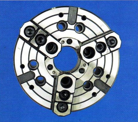
In the realm of CNC machining, it is imperative for chucks to deliver substantial initial gripping force, a consideration that MTPL addresses in the design by implementing a robust drawbar pull mechanism. Consequently, the wedge is designed to establish a sizable contact area with the base jaws.
Furthermore, the weight of the chuck body, base jaws, and hard jaws has been reduced without compromising other essential criteria. The chuck body is expertly crafted from forged steel, and the guideways have been hardened and ground.
The wedge, constructed from nickel-chrome steel, undergoes case hardening and thorough grinding across all working surfaces. Similarly, the base jaws, crafted from nickel-chrome steel, undergo case hardening and precise grinding to achieve alignment with both the wedge and the body’s guideways.
These base jaws are securely guided within the deep, expansive, and hardened slots within the body, which provide the necessary ample bearing area to withstand the forces generated during high-gripping operations. Additionally, provisions have been made for manual lubrication of the sliding surfaces through grease nipples.
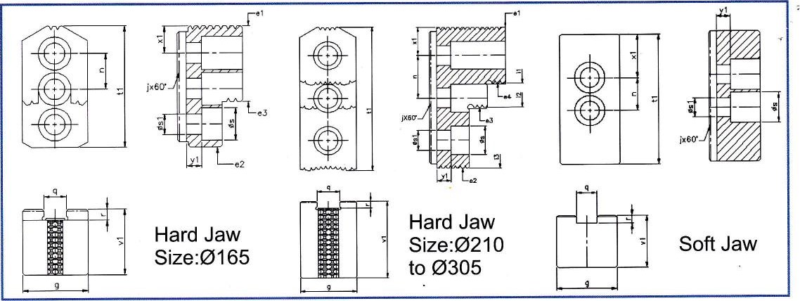
Furthermore, serrations are carefully ground onto the top face of the base jaws, while the reversible hard jaws feature corresponding ground serrations on their undersides. This serration configuration, combined with various radii on the hard jaws, is meticulously designed to accommodate a wide range of diameters.
Collectively, the hardened guideways of the body, nickel-chrome case-hardened and ground base jaws, and the wedge ensure a remarkable load-carrying capacity.
| Chuck Performance Detail | 2 Jaw & 4 Jaw chucks with through bore are available on request | ||||||
|---|---|---|---|---|---|---|---|
| Chuck Size Ø | 165 | 210 | 254 | 305 | |||
| Clamping Range | External | Max | 165 | 210 | 254 | 305 | |
| Min | 16 | 38 | 23 | 55 | |||
| Internal | Max | 165 | 210 | 254 | 305 | ||
| Min | - | 118 | 106 | 130 | |||
| Max drawbar pull (KGF) | 2200 | 3400 | 4300 | 4800 | |||
| Max gripping force (KGF) | 5400 | 8400 | 9300 | 11900 | |||
| RPM max | 6000 | 4800 | 4200 | 3300 | |||
| Weight (KGS) | 12 | 23 | 34 | 47 | |||
| Flywheel effect GD² (KPM²) | 0.2 | 0.38 | 0.8 | 2.6 | |||
| Max top jaw weight (KGS) | 1.5 | 1.7 | 3.5 | 4 | |||

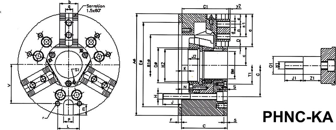
| DIMENSIONAL SPECIFICATION | All Dimensions are in mm | ||||
|---|---|---|---|---|---|
| Model | 67-01 | 67-02 | 67-03 | 67-04 | |
| Size Ø | 165 | 210 | 254 | 305 | |
| AØ | 169 | 210 | 254 | 304 | |
| BØ H7 | 45 | 52 | 78 | 91 | |
| B1Ø | 100 | 116 | 145 | 163 | |
| C | 76 | 86 | 95 | 104 | |
| C1 | 80 | 88 | 97 | 108.5 | |
| D Jaw Stroke | 2.75 | 3.7 | 4.4 | 5.3 | |
| EØ H6 | 140 | 170 | 220 | 220 | |
| F | 5 | 5 | 6 | 6 | |
| G PCD | 104.8 | 133.4 | 171.4 | 171.4 | |
| H | 6xM10 | 6xM12 | 6xM16 | 6xM16 | |
| H2 | M52x2 | M60x2 | M85x2 | M100x2 | |
| J | 15 | 17 | 23 | 24 | |
| J2 | 19 | 20.5 | 25 | 28 | |
| K min. | 0 | -1.5 | -10.5 | 8 | |
| K max. | 12 | 14.5 | 8.5 | -15 | |
| N | 12 | 16 | 19 | 23 | |
| OØ | 57 | 66 | 94.5 | 108 | |
| S1 | M5 | M6 | M6 | M6 | |
| Tl PCD | 63 | 72 | 99 | 117 | |
| a | 52.5 | 66 | 75 | 90 | |
| b | 30 | 40 | 45 | 50 | |
| c mm. | 29.25 | 35 | 48.6 | 56.7 | |
| c max. | 32 | 38.7 | 53 | 62 | |
| d | M10 | M12 | M12 | M14 | |
| e min | 9 | 10 | 14 | 11 | |
| n | 20 | 25 | 30 | 30 | |
| n1 max. | 44 | 53 | 63 | 73 | |
| qH7 | 12 | 14 | 16 | 21 | |
| y2 | 2.5 | 2.5 | 2 | ||
| PH12 | 16 | 16 | 16 | 20 | |
| r | M8 | M8 | M10 | M10 | |
| m | 18 | 28 | 30 | 55 | |
| L | 36 | 45 | 60 | 60 | |
| V | 65 | 85 | 105 | 125 | |
| Special Execution | |||||
| O1Ø | 31.5 | 35 | 35 | 35 | |
| HI | M16 | M20 | M20 | M20 | |
| J1 | 30 | 30 | 40 | 40 | |
| Z1 | 25 | 30 | 30 | 30 | |

| HARD JAW SPECIFICATIONS | |||||
|---|---|---|---|---|---|
| Ø-Size | 165 | 210 | 254 | 305 | |
| g | 35 | 35 | 40 | 50 | |
| j x 60° | 1.5 | 1.5 | 1.5 | 1.5 | |
| n | 20 | 25 | 30 | 30 | |
| qH7 | 12 | 14 | 16 | 21 | |
| r | 5 | 5 | 5 | 5 | |
| Øs | 17.5 | 20 | 20 | 26 | |
| Øs1 | 11 | 14 | 14 | 18 | |
| t1 | 67 | 86 | 101.5 | 97.5 | |
| v1 | 36 | 51 | 54 | 55 | |
| x1 | 14.5 | 17 | 20 | 16.5 | |
| y1 | 8 | 8 | 10 | 10 |
| SOFT JAW SPECIFICATIONS | |||||
|---|---|---|---|---|---|
| Ø-Size | 165 | 210 | 254 | 305 | |
| G | 35 | 35 | 40 | 50 | |
| j x 60° | 1.5 | 1.5 | 1.5 | 1.5 | |
| N | 20 | 25 | 30 | 30 | |
| q+0.05 | 12 | 14 | 16 | 21 | |
| R | 4.5 | 5 | 5 | 5 | |
| Øs | 17.5 | 20 | 20 | 23 | |
| Øs1 | 11 | 14 | 14 | 15 | |
| t1 | 75 | 95 | 110 | 129 | |
| v1 | 30 | 38 | 42 | 50 | |
| x1 | 20 | 24 | 30 | 39 | |
| y1 | 8 | 10 | 10 | 15 |
| HARD JAW CLAMPING RANGE | ||||
|---|---|---|---|---|
| Ø-Size | 165 | 210 | 254 | 305 |
| e1 | 16-81 | 40-130 | 23-124 | 55-182 |
| e2 | - | 38-127 | 23-124 | - |
| e3 | 70-134 | 95-184 | 109-210 | - |
| e4 | - | 135-210 | 143-244 | 175-302 |
| i1 | - | 118-206 | 106-206 | 130-252 |
| i2 | - | 157-210 | 141-240 | - |
| i3 | - | - | 227-254 | - |
