PHNC – Power Operated Three Jaw Chuck with Through Bore
Microturners Power-Operated Hollow High-Speed Chucks have been specifically engineered for high-speed rotation on CNC lathes. The streamlined design of the PHNC Chucks provides additional benefits such as reduced weight and minimal inertia, both of which significantly enhance the dynamic performance of CNC machine spindles. These chucks boast a substantial through bore, making them particularly well-suited for bar machining applications. Furthermore, the weight of the base jaws and top jaws has been minimised in these chucks, resulting in not only reduced mass but also a lowered center of gravity, thereby minimising centrifugal losses.
In CNC machining, it’s essential for chucks to deliver substantial initial gripping force, and Microturners addresses this requirement by designing the chuck to operate with a high drawbar pull. Consequently, the wedge is designed to establish a substantial contact area with the base jaws.
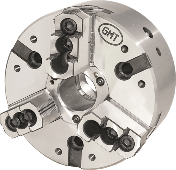
Furthermore, the chuck body, base jaws, and hard jaws have been meticulously engineered to reduce weight without compromising other essential criteria.
Notably, the chuck body is forged from steel, and the guideways are hardened and ground for optimal performance.
Additionally, in larger sizes ranging from 250 mm to 500 mm, the chuck body has been recessed to remove a significant amount of material, further reducing its weight.
Four Jaw Hand Operated Independent Chuck
The GMT four-jaw chuck boasts several key attributes that set it apart from other four-jaw independent chucks on the market.
To begin with, the chuck body is meticulously crafted from forged medium-carbon steel, a material that undergoes a process of hardening and tempering to ensure both longevity and structural integrity. The base jaw slots within the body are precision-ground to exacting tolerances, enabling a snug sliding fit.
This precision engineering guarantees a play-free operation, remarkable load-bearing capability, and optimal wear resistance.
What truly distinguishes GMT’s independent four-jaw chuck system is the provision of separate jaws and reversible hard jaws. This design feature grants the flexibility to employ specialized hard jaws tailored to specific components.
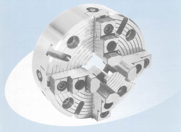
Furthermore, the base jaws are meticuously fashioned from alloy steel and subjected to case hardening. They are designed to be deeper and wider, thereby providing substantial bearing areas with reduced unit bearing pressure. This design enhancement significantly extends the chuck’s operational lifespan.
Another notable feature is the incorporation of square threads on the screws and the undersides of the base jaws. These threads engage more extensively, resulting in efficient transmission and conversion of applied torque. The screws themselves undergo heat treatment to prevent breakage, addressing a common concern in commercial-quality chucks.
The wedge, crafted from nickel-chrome steel, undergoes case hardening and precision grinding on all its operational surfaces. Likewise, the base jaws, also fashioned from nickel-chrome steel, undergo case hardening and precise grinding to achieve alignment with both the wedge and the body’s guideways.
These base jaws are expertly guided within the deep, expansive, and hardened slots within the body. These slots provide the ample bearing surface necessary to endure the forces generated during high gripping operations. Additionally, provision has been incorporated for manual lubrication of the sliding surfaces via grease nipples.
Furthermore, the top face of the base jaws features meticulously ground serrations, and the reversible hard jaws possess corresponding ground serrations on their undersides. This serration configuration, combined with various radii on the hard jaws, is carefully designed to accommodate a wide range of diameters.
The body’s hardened guideways, along with the nickel-chrome case-hardened and ground base jaws and wedge, collectively ensure a remarkable load-bearing capacity over an extended operational lifespan.
Chuck Performance Detail
2 Jaw & 4 Jaw chucks with through bore can be offered on request
| Chuck Size Ø | 135 | 165 | 200 | 250 | 315 | 400 | 500 | ||
|---|---|---|---|---|---|---|---|---|---|
| Clamping Range | External | Max | 128 | 165 | 200 | 250 | 315 | 400 | 500 |
| Min | 10 | 32 | 25 | 28 | 42 | 45 | 74 | ||
| Internal | Max | - | 165 | 200 | 250 | 315 | 400 | 500 | |
| Min | - | 62 | 70 | 76 | 84 | 105 | 138 | ||
| Max drawbar pull (KGF) | 1780 | 2000 | 4000 | 6000 | 6000 | 9000 | 9000 | ||
| Max gripping force (KGF) | 3670 | 5400 | 8000 | 12000 | 13000 | 20000 | 21000 | ||
| RPM max | 7000 | 5000 | 5000 | 4000 | 3200 | 2500 | 2000 | ||
| Weight - without top jaws (KGS) | 6 | 12.5 | 19 | 29 | 42 | 88 | 164 | ||
| Flywheel effect GDL (KPML) | 0.17 | 0.2 | 0.38 | 0.8 | 2.6 | 8.4 | 24.8 | ||
| Max top jaws weight per set (KGS) | 0.4 | 1.5 | 1 | 3.5 | 4 | 7.5 | 7.5 | ||
Dimensional Specification
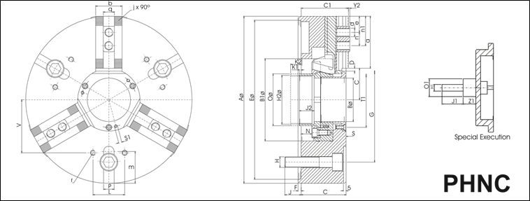
All dimentions are in mm
| Model | 04-69 | 04-70 | 04-82 | 04-83 | 04-84 | 04-85 | 04-86 |
|---|---|---|---|---|---|---|---|
| Size Ø | 135 | 165 | 200 | 250 | 315 | 400 | 500 |
| A Ø | 135 | 165 | 200 | 250 | 315 | 400 | 500 |
| B Ø h7 | 33 | 35 | 48 | 65 | 82 | 120 | 160 |
| B1 | 80 | 90 | 110 | 135 | 155 | 210 | 250 |
| C | 56 | 77 | 85 | 88 | 85 | 120 | 120 |
| Cl | 58 | 82 | 89 | 92 | 89.5 | 125 | 125.5 |
| D Jaw Stroke | 2.7 | 3.15 | 5.3 | 5.3 | 5.3 | 8 | 8 |
| E Ø H6 | 110 | 140 | 170 | 220 | 300 | 380 | 380 |
| F | 4 | 5 | 6 | 6 | 6 | 6 | 6 |
| G PCD | 82.6 | 104.8 | 133.4 | 171.4 | 235 | 330.2 | 330.2 |
| H | 3 x M10 | 6x M10 | 3 x M12 | 3 x M16 | 3 x M20 | 3 x M24 | 6xM24 |
| Hl | M12 | M16 | M20 | M20 | M20 | M 30 | M 30 |
| H2 | M40x 1.5 | M42x 1.5 | M55 x 2 | M72x 2 | M92x 2 | M133 x 2 | M172x 3 |
| J | 15 | 14 | 18 | 24 | 31 | 31 | 36 |
| J1 | 43 | 55 | 55 | 55 | 55 | 54 | 54 |
| J2 | 20 | 27 | 28 | 28 | 28 | 28 | 28 |
| Kl max | -1.8 | 5 | 0.5 | 0.5 | 3.5 | -8.5 | -8.5 |
| K2 max | 8.1999999999999993 | 20 | 20.5 | 20.5 | 23.5 | 21.5 | 21.5 |
| N | 8.1999999999999993 | 15 | 20 | 20 | 20 | 30 | 30 |
| O | 48 | 48 | 62 | 78 | 98 | 142 | 182 |
| O1 | 27 | 30 | 35 | 35 | 35 | 46 | 46 |
| S | 6 | 8 | 8 | 8 | 8 | 12 | 12 |
| S1 | M4 | M5 | M6 | M6 | M6 | M8 | M8 |
| T1 PCD | 45 | 54 | 68 | 86 | 104 | 145 | 185 |
| Z1 | 25 | 25 | 30 | 30 | 30 | 30 | 30 |
| a | 41 | 50.7 | 59 | 76 | 98 | 118 | 150 |
| b | 27 | 35 | 40 | 45 | 50 | 60 | 60 |
| c min | 23.5 | 28.65 | 35.700000000000003 | 43.7 | 54.2 | 74 | 94 |
| c max | 26.5 | 31.8 | 41 | 49 | 59.5 | 82 | 102 |
| d | M8 | M10 | M12 | M16 | M16 | M20 | M20 |
| e min | 6.5 | 9 | 9 | 10 | 10 | 15 | 15 |
| j x 90° | 1/16" | 1/16" | 1/16" | 1/16" | 1/16" | 3/32" | 3/32" |
| n | 14 | 19 | 19 | 25 | 25 | 34 | 34 |
| n1 max | 31 | 38.5 | 50 | 60 | 85 | 103 | 130 |
| q H7 | 10 | 12 | 17 | 21 | 21 | 25.5 | 25.5 |
| y2 | 2 | 3 | 3.5 | 3.5 | 3.5 | 3.5 | 3.5 |
| PH12 | - | 16 | 16 | 16 | 20 | 20 | 20 |
| r | M6 | M8 | M8 | M1O | M1O | M12 | M12 |
| m | - | 18 | 23.5 | 26.5 | 60 | 60 | 115 |
| L | 30 | 36 | 45 | 60 | 60 | 80 | 100 |
| V | 52 | 65 | 80 | 105 | 125 | 155 | 170 |
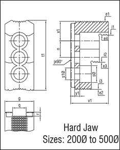
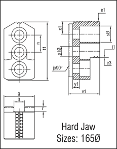
Hard Jaw Specification
All dimentions are in mm
| Size Ø | *135 | *165 | 200 | 250 | 315 | 400 | 500 |
|---|---|---|---|---|---|---|---|
| g | 23 | 35 | 35 | 45 | 50 | 60 | 60 |
| j x 90° | 1/16”x90° | 1/16”x90° | 1/16”x90° | 1/16”x90° | 1/16”x90° | 3/32”x90° | 3/32”x90° |
| n | 14 | 19 | 19 | 25 | 25 | 34 | 34 |
| qH7 | 10 | 12 | 17 | 21 | 21 | 25.5 | 25.5 |
| r | 4 | 4.5 | 5 | 6 | 6 | 6 | 6 |
| s Ø | 14.5 | 17.5 | 20 | 26 | 26 | 34 | 34 |
| sl Ø | 9 | 11 | 14 | 18 | 18 | 22 | 22 |
| tl | 53.4 | 64.77 | 73.27 | 106 | 104 | 142 | 142 |
| vl | 28.5 | 36 | 51 | 58 | 62 | 75 | 75 |
| xl | 12.5 | 14.5 | 17 | 29.5 | 30 | 45 | 45 |
| yl | 4.5 | 8 | 8 | 8 | 8 | 8 | 9 |
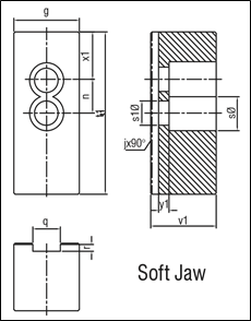
Soft Jaw Specification
All dimentions are in mm
| Size Ø | *135 | *165 | 200 | 250 | 315 | 400 | 500 |
|---|---|---|---|---|---|---|---|
| g | 23 | 35 | 35 | 45 | 50 | 60 | 60 |
| j x 90° | 1/16”x90° | 1/16”x90° | 1/16”x90° | 1/16”x90° | 1/16”x90° | 3/32”x90° | 3/32”x90° |
| n | 14 | 19 | 19 | 25 | 25 | 34 | 34 |
| q + 0.05 | 10 | 12 | 17 | 21 | 21 | 25.5 | 25.5 |
| R | 4 | 4.5 | 5 | 6 | 6 | 6 | 6 |
| s Ø | 14.5 | 17.5 | 20 | 26 | 26 | 34 | 34 |
| sl Ø | 9 | 11 | 14 | 18 | 18 | 22 | 22 |
| tl | 54 | 75 | 80 | 120 | 120 | 155 | 155 |
| vl | 25 | 30 | 40 | 50 | 50 | 60 | 60 |
| xl | 12 | 20 | 15 | 35 | 33 | 41 | 41 |
| yl | 5 | 8 | 8 | 8 | 8 | 12 | 12 |
Hard Jaw Clamping Range
All dimentions are in mm
| Size Ø | *135 | *165 | 200 | 250 | 315 | 400 | 500 |
|---|---|---|---|---|---|---|---|
| el | 10-47 | 25-78 | 25-99 | 28-104 | 42-170 | 45-205 | 74-290 |
| e2 | - | - | 25-102 | 41-124 | 56-195 | 80-240 | 112-336 |
| e3 | 76-128 | 78-155 | 74-152 | 123-206 | 135-252 | 200-354 | 226-450 |
| e4 | - | 124-200 | 205-250 | 220-315 | 298-400 | 330-500 | |
| il | - | 114-165 | 70-150 | 76-160 | 84-218 | 105-265 | 138-368 |
| i2 | - | - | 116-190 | 156-242 | 190-303 | 217-377 | 240-472 |
| I3 | - | - | 166-200 | 236-250 | 228-315 | 331-400 | 348-500 |
Cylinder Selection Chart For Phnc & Phcnc
All dimentions are in mm
| Size Ø | *135 | *165 | 200 | 250 | 315 | 400 | 500 |
|---|---|---|---|---|---|---|---|
| Hydraulic Cylinder CH-S | 105 | 120 | 120 | 160 | 200 | 250 | 250 |
| Hydraulic Hollow cylinder OCHNC-S | - | - | - | 170 | 170 | 200 | 200 |
| Hydraulic hollow cylinder SHS | 105 | 105 | 130 | 154 | - | - | - |
- Hard Jaws are common for PHNC & PHCNC
- Soft Jaws are supplied as blanks and are common for PHNC & PHCNC
- Only Soft Jaws are supplied with 2 Jaw Chucks
- Serration 1.5 x 60°, 3 x 60° on Base Jaws, Hard Jaws and Soft Jaws can be offered on request
- *Offered in PHNC only
